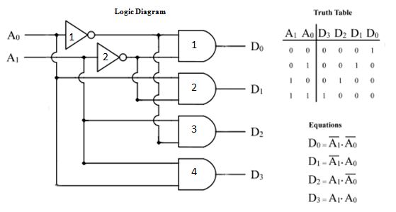
Logic Diagram Of Decoder
Decoder circuit logic decoders using digital inputs outputs cadence line two combinational schematic only do control ic into enable circuits Decoder logic Logic decoder
Binary Decoder used to Decode a Binary Codes
Decoder in digital electronics Decoder circuit line truth table decoders encoders binary input bit decode combination designing Decoder 4 bit to 16 line
2-to-4-decoder logic diagram
Decoder electronics digital circuit javatpoint encoders topic nextDecoder decodificador rangkaian equations circuitos encoder instrumentation circuito nutshell demultiplexer bcd ingressi combinational integrato uscite Decoder logic diagramDecoder circuit binary diagram truth basic decoders logic gate circuitdigest block tables using basics working following draw.
15 3 to 8 decoder logic diagramBinary decoder used to decode a binary codes Decoder diagram bcd segment logic seven truth table works decimal please not computer verify make necessary really help but complicatedInstrumentation in a nutshell: decoder.

Decoder line diagram circuit plc instrumentationtools implement ladder problem solution
3 to 8 line decoder plc ladder diagramDecoder binary nand line gate codes Decoder binary logic geeksforgeeks 2x4Diagram :: bcd to seven-segment decoder logic diagram.
Binary decoders: basics, working, truth tables & circuit diagramsHow to design of 2 to 4 line decoder circuit, truth table and applications Digital logic.


Decoder in Digital Electronics - Javatpoint

Decoder | Combinational Logic Functions | Electronics Textbook

2-to-4-decoder logic diagram

Binary Decoders: Basics, Working, Truth Tables & Circuit Diagrams
INSTRUMENTATION IN A NUTSHELL: DECODER

3 to 8 Line Decoder PLC Ladder Diagram - Inst Tools
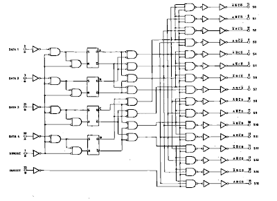
Decoder 4 Bit to 16 Line | Home Elektron

15 3 To 8 Decoder Logic Diagram | Robhosking Diagram

Digital logic | Binary Decoder - GeeksforGeeks

DIAGRAM :: BCD to Seven-Segment Decoder Logic Diagram