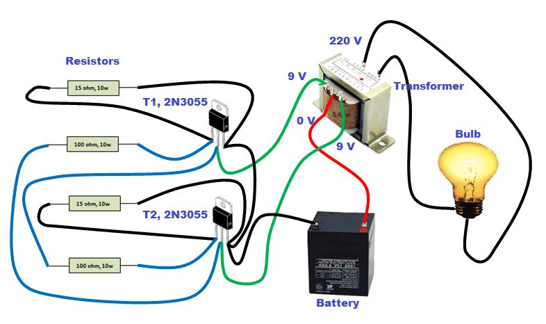
Inverter Connection Circuit Diagram
Inverter phase circuit three 120 degree mode conduction diagram dc dilip raja nov 12v dc to 220v ac inverter circuit & pcb Inverter mains ups
Modified Sine Wave Inverter Circuit Using IC 3525, with Regulated
Inverter timer 230v 240v The ladder wave inverter output three-phase transformer winding Inverter circuit wave sine sg3525 using modified ic 3525 protection low diagram output power battery board projects watt simple control
Operation of 200 watt inverter diagram – electronic projects circuits
12v to 230v inverter circuit diagram using 555 timer ic » invertersInverter 220v how2electronics Phase circuit transformer inverter three output waveform wave connection diagram winding ladder voltage power seekic shown figureSimple inverter circuit diagram.
Inverter circuit 12v circuits 230v coupledInterlocking gate drivers for improving the robustness of three-phase Circuit inverter transistors circuits explanationInverter connection step by step.

Home inverter connection diagram pdf
Inverter circuit diagram board7 simple inverter circuits you can build at home Easy inverter circuit with 2sc1815 transistorsInverter wiring homemade pwm induction heater circuits ic.
Three phase inverter circuit diagramModified sine wave inverter circuit using ic 3525, with regulated Inverter connection to mainsDiagram block inverter inverters watt 200watt circuit mosfet output circuits electronic operation control 50hz high eleccircuit projects figure.
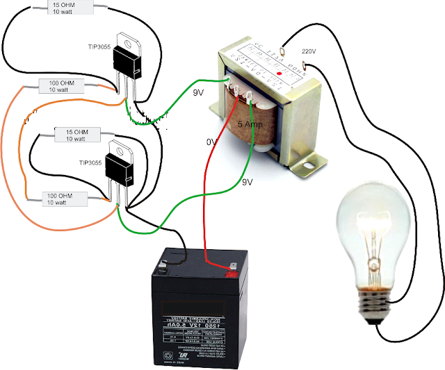
Diagram connection inverter wiring motor drive switch connect connected
Inverter electrical wiring rangkaian circuits sederhana skema 220v listrik pilas baterias joule thief kabel newcomers baru transformer circuito decentInverter rangkaian dc sederhana electricalfundablog 12v connections schematics ct populer terbaru gaya skema transformer Inverter wiring diagram ups connection switch electrical circuit bypass house wire office room pdf single diagrams outlet board line systemPhase three gate inverter inverters isolated drivers ti industrial vfd robustness interlocking improving schematic 3phase figure technical.
14+ inverter connection diagram .
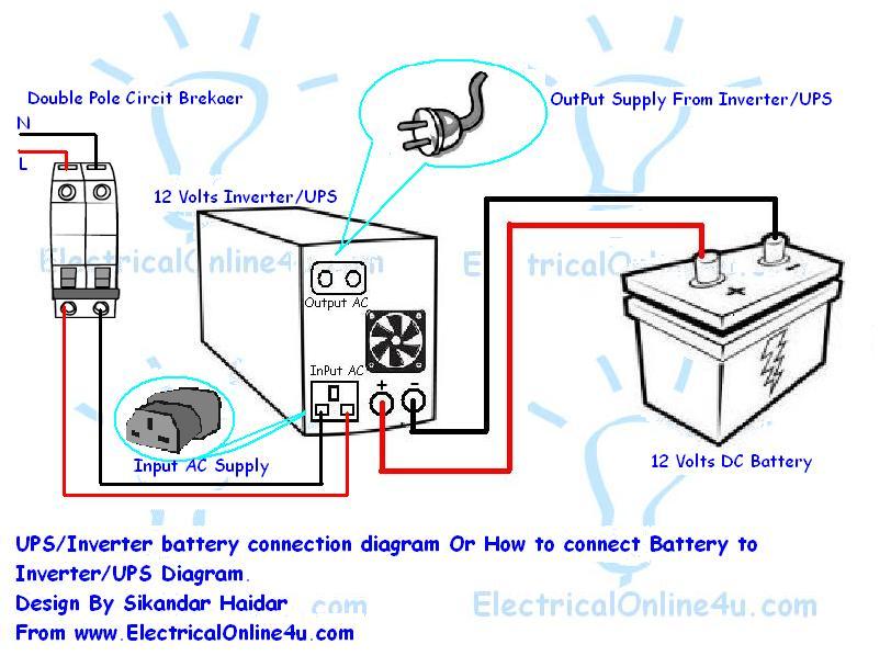
Inverter Connection Step By Step | Home Wiring Diagram
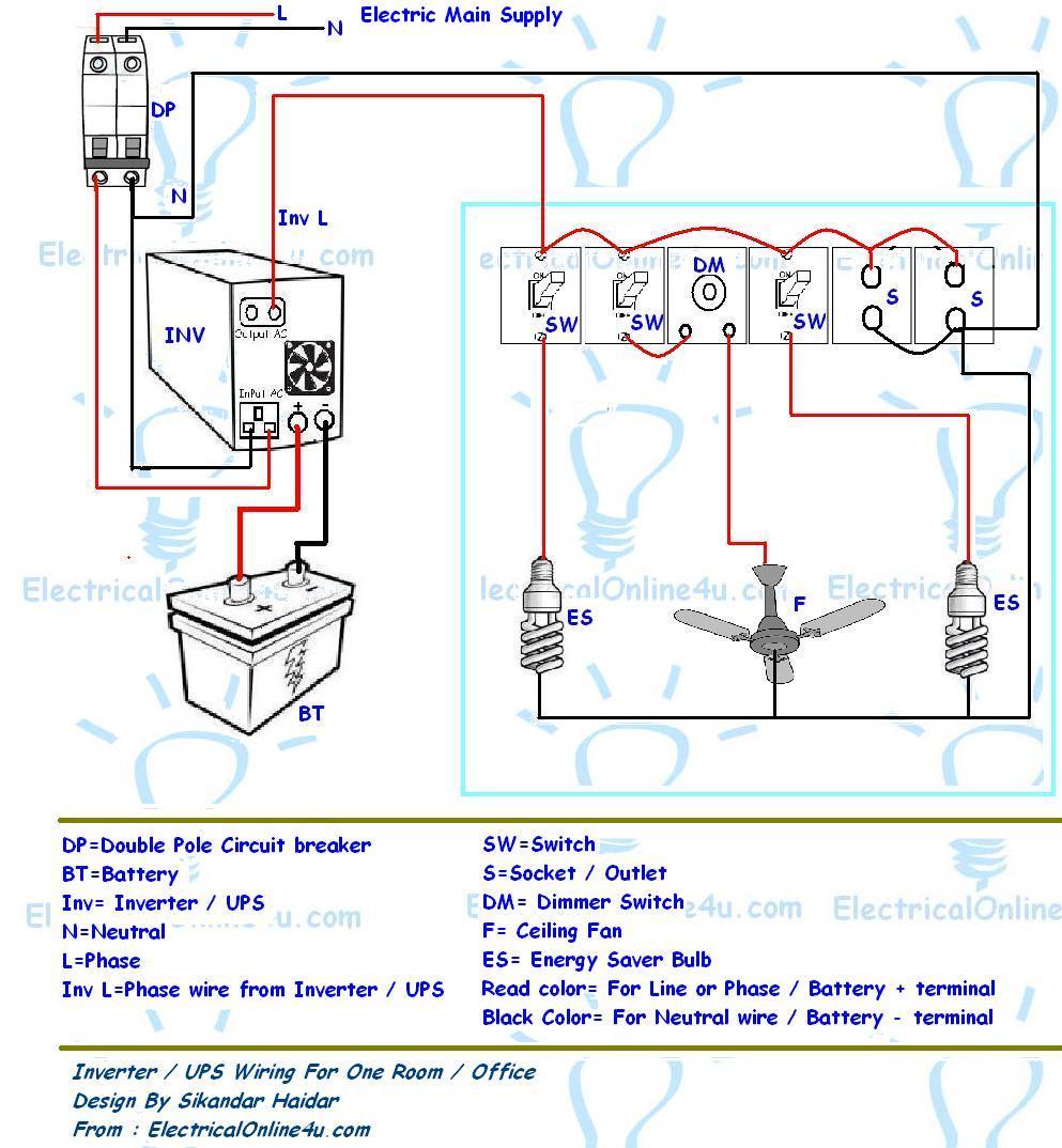
Home Inverter Connection Diagram Pdf | Home Wiring Diagram

Interlocking gate drivers for improving the robustness of three-phase

Easy Inverter Circuit with 2SC1815 Transistors

12V DC to 220V AC Inverter Circuit & PCB

Three Phase Inverter Circuit Diagram - 120 Degree and 180 Degree

Modified Sine Wave Inverter Circuit Using IC 3525, with Regulated

12V to 230V Inverter Circuit Diagram using 555 timer IC » Inverters
14+ Inverter Connection Diagram | Robhosking Diagram